NEMA Wiring Diagram Guide for Electrical Experts
About 70% of the electrical malfunctions across facilities are due to poor wiring methods. This fact emphasizes the requirement of adhering to recognized protocols, highlighting NEMA wiring schematics’ value for electrical experts. By means of these diagrams, wiring configurations that satisfy both operational effectiveness and supreme protection criteria are delineated.
The aim of this manual is to arm electrical practitioners with comprehensive insights into NEMA norms. Emphasizing the importance of correct electrical arrangements is vital. By mastering these guidelines, specialists can substantially minimize the risk of hazards and confirm they comply with safety protocols endorsed by Installation Parts Supply. Expertise in NEMA l14-30R wiring diagram is essential whether creating modern networks or fixing current ones, as it boosts the capacity to offer safe and trustworthy electrical solutions.
Central Ideas
- NEMA wiring diagrams are vital for guaranteeing electrical protection and adherence.
- Proper wiring methods can minimize electrical failures substantially.
- Comprehending NEMA criteria boosts the performance of electrical arrangements.
- Installation Parts Supply promotes following safety standards in electrical work.
- NEMA schematics cover a variety of uses across multiple industries.
Grasping NEMA Norms and Why They Matter
NEMA standards are pivotal in the electrical field, guiding protection and functionality precisely. Developed by the National Electrical Manufacturers Association, they establish critical criteria for designing, evaluating, and labeling electrical gear. This ensures consistency and trustworthiness across all electrical set-ups, which is of great value.
Which Are NEMA Norms?
NEMA designations vary from grades 1 through 13. Every level delineates the conditions required for electrical appliances to perform optimally. Such as, NEMA 1 delivers minimal indoor protection but lacks dust shielding. On the other hand, NEMA 4 guarantees appliances is sealed, a necessity for enduring substantial water exposure. Understanding these classifications is essential in selecting proper devices.
How NEMA Criteria Matter for Electrical Protection
The role of NEMA criteria in ensuring electrical protection is substantial. They contribute greatly in reducing electric shock, apparatus failures, and fire hazards. Proper adherence to NEMA standards allows devices to perform securely under specific ambient conditions. For external application, NEMA 3 classifications offer protection against the elements, shielding the device from adverse climate like precipitation and snowfall. In areas susceptible to explosions, standards including NEMA 7, 8, and 9 are vital for ensuring safety.
Applications of NEMA Standards in Wiring Schematics
The use of NEMA standards in wiring drawings is crucial for protected, efficient electrical setups. These diagrams employ standardized symbols and structures originating from NEMA classifications, facilitating the understanding of detailed electrical setups. This uniformity is advantageous. It encourages clarity, uniformity, and reduces misinterpretations, thereby enhancing electrical security across residential and factory landscapes.
NEMA Wiring Schematic Essentials
NEMA wiring schematics are essential for electrical experts, rendering intricate linkages transparent. They outline the linkages and parts in diverse configurations. By comprehending the parts, types, and notations of NEMA schematics, electricians can enhance their work in setups and maintenance.
Constituents of NEMA Wiring Schematics
NEMA drawings comprise key parts for distinct electrical installations. You’ll discover wiring terminals, connectors, and various equipment for safe junctions. Every piece guarantees energy is spread efficiently, in accordance with security standards.
Varieties of NEMA Wiring Diagrams
NEMA uses various schematics, like connection blueprints and electrical designs. Such diagrams outline device associations, while layouts illustrate current flow. Opting for the correct schematic helps with problem solving and deployment.
Common Icons Found in NEMA Wiring Diagrams
Symbols in wiring diagrams are crucial for unambiguous communication. They represent controls, circuits, and couplers. Knowing these icons assists crews read diagrams accurately. Such practice ensures installations comply with NEMA norms.
NEMA Wiring Schematic Features
For electrical specialists, comprehending the fundamental components of precise electrical wiring schematics is crucial. These diagrams offer both clarity and thoroughness, aligning configurations with NEMA norms. They necessitate precise marking and proportioning to minimize setup mistakes. This encourages a protected and more efficient workplace.
Primary Attributes of Precise Electrical Wiring Drawings
Correct electrical wiring schematics are essential in electrical initiatives. They encompass key attributes such as:
- Clarity: Diagrams must be simple, reducing the risk of misinterpretation.
- Completeness: They must include all key elements, linkages, and electrical standards.
- Adherence to Standards: Adherence to NEMA norms is non-negotiable for guaranteeing protection and functionality.
- Thorough Annotation: Unambiguous annotations on each component are fundamental for comprehension and error prevention.
- Proper Sizing: The scales should reflect the actual setup to represent the configuration precisely.
Grasping NEMA Coupler Pinout
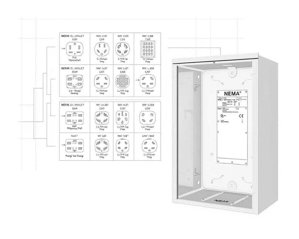
The insight into NEMA connector layout is vital for forming proper connections in electrical setups. Awareness of specific pin configurations ensures safety and appliance performance. There are a diversity of NEMA interfaces, crafted for different voltages and amperages, encompassing:
| NEMA Connector Type | Current Rating | Power Rating |
|---|---|---|
| L5-15 | 15A | 125V |
| L5-20 | 20A | 125V |
| L14-20 | 20A | 125/250V |
| L1430C | 30A | 125/250V |
| L620C | 20A | 250V |
| L1430C | 30A | 125/250V |
| L630R | 30A | 250V |
Understanding NEMA coupler layouts is vital for secure linkages, enhancing efficiency. It’s paramount to align couplers with equipment correctly using rotary-lock or linear blade variants, to avoid safety risks.
NEMA Device Wiring
NEMA appliance wiring encompasses multiple configurations for protected electrical device interfaces. These rules guarantee that devices integrate securely, reducing danger. Knowing the different NEMA equipment and their wiring is essential for specialists.
Different Categories of NEMA Units
NEMA categorizes devices by kind based on voltage and flow needs. Essential setups are:
- 2-Pole, 2-Wire
- 2-Pole 3-Wire Grounding
- 3-Pole, 3-Wire
- 3-Pole, 4-Wire with Grounding
- 4-Pole 4-Wire
- 4-Pole 5-Wire Grounding
These setups are employed in domestic settings and manufacturing plants, handling 125V, 208V, and 480V.
NEMA Outlet Wiring Demystified
NEMA plug wiring changes to suit diverse electrical demands, with twist-lock types providing consistent connections in shaky settings. For instance, the L5-15 plug is rated for 15 A, typical of business sites, whereas the L14-20 is crafted for 20 amperes at 125/250 volts.
The NEMA labeling convention aids in choosing the right plugs, highlighting characteristics like charge orientation and grounding. This precision guarantees that equipment perform reliably.
NEMA Receptacle Wiring Instructions
Correct wiring of NEMA receptacles meets electrical regulations and safety guidelines. For example, L530R receptacles are rated for 30 amperes at 125 volts, with L630R variants for 250 V. Correct grounding is crucial to prevent electrical accidents.
Opting for approved NEMA plugs and sockets guarantees safe, code-compliant configurations. It’s vital to check authoritative guidelines when implementing.
NEMA Motor Wiring and Applications
NEMA motor wiring is crucial in electrical engineering, particularly for industrial use. Grasping how NEMA motor configuration works ensures that machines are set up for peak operation. Such devices, like one-phase and tri-phase models, demand correct wiring to operate securely and optimally.
Introduction of NEMA Motor Wiring
Understanding NEMA motor wiring necessitates familiarity of linkages and configurations. The majority of three-phase motors now support dual-voltage, meaning they can work on both low (208-230V) and high voltage levels (460V). Wiring at high voltage allows motors to draw less current than at low voltage. High voltage perks include reduced gauge wiring for the input, a significant benefit for engines above 10 HP.
While both NEMA and IEC units are employed in the sector, NEMA variants are usually larger and more expensive than IEC ones for under 100 HP applications. NEMA controllers vary from size 00 to 9, fit for multiple applications. A standard feature in NEMA controllers is a Trip Rating of 20, designed to trip when a motor’s current surpasses 6-fold the rated current in 10 secs.
Choosing the Appropriate NEMA Motor Configuration
Choosing the right NEMA motor arrangement impacts system efficiency and safety. A common three-wire control circuit employs three wires for a start/stop pushbutton station, facilitating simple motor management. Common three-phase configurations comprise the 12 Lead Dual Voltage and 6 Lead, supporting Wye and Delta configurations.
IEC motor starters often include phase monitoring, enhancing safety. They also feature modifiable Fault Classes for tailored protection in low voltage operations. Moreover, many units have temperature safeguards, vital for single-phase and Dual Voltage configurations.
| Arrangement | Voltage Type | Current Rating | Common Application |
|---|---|---|---|
| 12 Lead Dual Voltage | Dual Voltage (208-230V / 460V) | Varies by motor size | Wye Start – Delta Run applications |
| 6 Lead | Single or Dual Voltage | Maximum 32A | Wye/Delta configurations |
| Single Phase | One Voltage | Ranges from 1 to 5 amps | Applications with Two Speed, Two Winding |
| Delta Connection | High-Power Voltage | Based on configuration | Current Transformers, multiple configurations |
The Bottom Line
Grasping NEMA wiring drawings and norms is vital for electrical professionals aiming to improve their capabilities and adhere to electrical security guidelines. These principles secure protected and high-performing electrical setups but also avoid dangers associated with incorrect wiring. In summary, adhering to NEMA criteria leads to the improved performance of diverse NEMA devices and systems.
For electricians, the availability of high-quality resources can profoundly influence the outcome of their tasks. Installation Parts Supply provides a extensive selection of wiring items in accordance with NEMA criteria. This allows specialists to access essential components for complying with these significant regulations. High-quality materials and profound knowledge of NEMA wiring diagrams significantly elevate project security and effectiveness.
In your journey through electrical installations, always place safety and precision above all. Mastering NEMA norms delivers the knowledge necessary for executing best practices accurately. This secures that each electrical connection made meets high-quality criteria.
FAQ
Which are NEMA wiring diagrams?
NEMA wiring schematics illustrate the setups and connections of NEMA-standard electrical appliances. They comply with safety and operational norms set by the National Electrical Manufacturers Association.
Why are NEMA standards important for electrical security?
NEMA norms are key to setting safety and performance criteria for electrical devices. These guidelines assist electrical professionals minimize electrocution risks, operational errors, and fire risk.
Which elements are essential in a NEMA wiring drawing?
Fundamental parts in a NEMA wiring schematic consist of circuit setups and junction blueprints. These drawings also feature detailed markings and show the electrical system’s various parts accurately for installations.
What types of NEMA wiring drawings exist?
Diverse NEMA wiring schematics address different applications, including energy distribution layouts and connector schematics. Every design serves a unique role in electrical systems.
Identify the common symbols used in NEMA wiring diagrams?
Typical symbols in these drawings symbolize switches, fuses, receptacles, and more. Employing these symbols facilitates clear communication and correct understanding of wiring schematics.
Which are the essential attributes of accurate electrical wiring schematics?
Precision in electrical wiring drawings is marked by their clarity, thoroughness, and explicit labeling. They need to meet NEMA standards to prevent faults in setup.
What is a NEMA connector layout?
A NEMA connector configuration outlines electrical linkages at a connector, indicating particular pin assignments. This guarantees safe and efficient junctions in electrical systems.
What are the different types of NEMA devices?
NEMA devices consist of various electrical receptacles and couplers, like connectors and sockets. They are crafted for different ampere and voltage levels specifications to satisfy specific usage needs.
Describe how NEMA plug wiring arranged?
NEMA plug wiring hinges on defined amperage and voltage needs, complying with safety standards and electrical codes for diverse electrical applications.
Identify the recommendations are there for NEMA receptacle wiring?
Standards for installing NEMA outlets stress following electrical codes, guaranteeing correct electrical polarity, and picking proper wire sizes. This sustains both safety and performance in electrical configurations.
How can I wire a NEMA motor effectively?
To wire a NEMA motor, one must comprehend its particular one-phase or tri-phase configuration. Opting for the right wiring approach is crucial, in addition to observing electrical safety for enhanced motor functionality.
Which factors should be considered when selecting a NEMA motor setup?
Selecting a NEMA motor configuration necessitates an evaluation of the project’s voltage and current demands and operational characteristics. It’s also essential to confirm alignment with current systems for guaranteed operation and protection.